
Short answer
An accumulation tank connection diagram shows where the tank joins the system: cold water inlet at the bottom, hot water outlet at the top, the supply and return lines of the heat source (boiler, solar system, heat pump or water heater), the recirculation port and the thermometer/anode pockets. The tank produces no heat of its own; it only stores it. Water from the boiler or heat pump circuit never mixes with the domestic water; heat is transferred through a plate heat exchanger or a coil-type water heater. A correct connection also preserves stratification, the natural layering of hot water above cold; break it and the stored hot water runs out faster. Below you will find the ports in a table, the typical connection order for boiler and heat pump systems, and the installation rules that matter. For what an accumulation tank is and how it works, see what is an accumulation tank; for the product family, see the Accumulation Tank page.
How to read an accumulation tank connection diagram
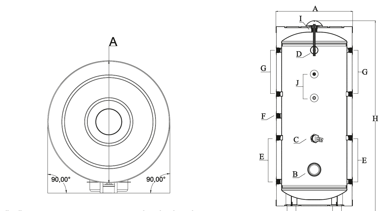
An accumulation tank connection diagram maps the ports on the tank body to the circuit each one serves. Their positions are not random: hot water is lighter and collects at the top of the tank, cold water stays at the bottom. Where each line enters and leaves therefore directly affects how efficiently the tank stores heat.
Omega accumulation tanks are built with an enamel inner lining, cathodic protection (anode rod) and a thermometer; all three appear on the diagram as their own ports or pockets. The table below summarises the ports on a typical accumulation tank.
| Port | Position | Function |
|---|---|---|
| Cold water inlet | Lower tank | Feeds cold water from the mains or booster line; a bottom entry keeps the hot top layer undisturbed. |
| Hot water outlet | Upper tank | Sends the hottest stored water to taps, showers and the domestic line. |
| Heat source inlet | Upper-middle zone | Delivers domestic water heated in the exchanger or water heater into the tank. |
| Heat source return | Lower tank | Sends the cold water at the bottom of the tank back to the charge circuit (exchanger) for reheating. |
| Recirculation inlet | Side or upper zone | Keeps hot water moving through the domestic line so taps deliver hot water instantly. |
| Thermometer/sensor pocket | Upper zone | Reads the stored water temperature for the gauge or control system. |
| Cathodic protection port | Top cover or flange | Mounting point of the anode rod that protects the tank where the enamel is weakest. |
| Drain valve | Lowest point | Fully empties the tank for service, decommissioning or winter drain-down. |
| Safety relief valve port | On the cold inlet line | Relieves the pressure rise that comes with heating, protecting the tank. |
Omega accumulation tanks are rated for 90 °C water temperature, 10 bar working pressure and 13 bar test pressure; valves, pumps and safety fittings on the connected lines must be selected to match.
Accumulation tank connection diagram in a boiler system
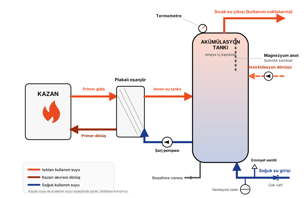 Accumulation tank connection diagram in a boiler system: boiler, plate heat exchanger, charge pump and domestic hot water line
In a boiler system the usual setup has the boiler heating domestic water through a plate heat exchanger, with the accumulation tank storing that water and feeding the domestic line. Boiler circuit water and the domestic water in the tank are separated in the exchanger and never mix. The connection order runs as follows:
- Connect the boiler's supply and return lines to the primary side of the plate heat exchanger; this circuit runs on its own circulation pump.
- Draw cold water from the return port at the bottom of the tank and pass it through the secondary side of the exchanger with the charge pump.
- Feed the water heated in the exchanger into the heat source inlet in the upper-middle zone of the tank.
- Connect the cold water from the mains or booster set to the cold inlet at the bottom of the tank.
- Connect the hot water outlet at the top to the building's domestic line (taps, showers, fixtures); if there is a recirculation line, take it from the far end of the line and return it to the recirculation inlet.
- Mount the safety relief valve on the cold inlet line, between the tank and the inlet valve.
Instead of a plate heat exchanger, a coil-type water heater can take over the separation duty: the boiler connects to the water heater's coil, the water heater heats the water and the accumulation tank stores it. This series arrangement is preferred in facilities with high peak demand, such as hotels and hospitals. For the water heater's own connection order, see our water heater connection diagram article.
Accumulation tank connection diagram in a heat pump system
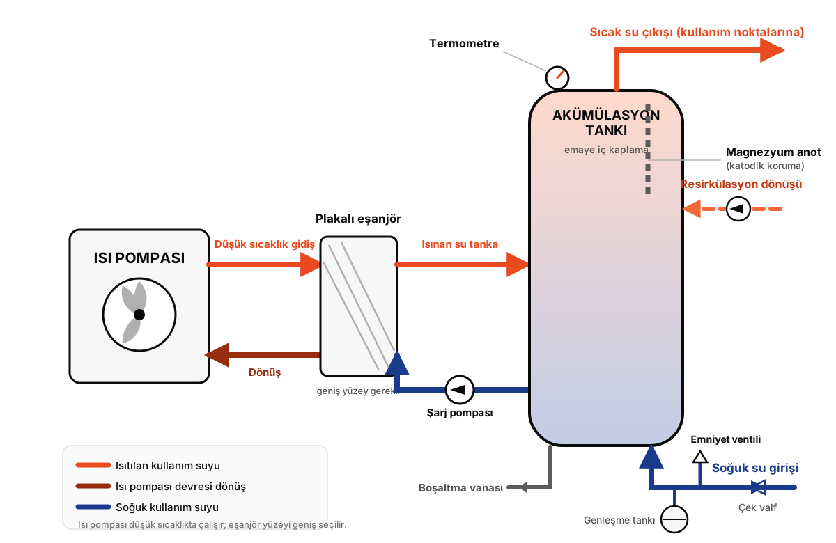 Accumulation tank connection diagram in a heat pump system: heat pump, plate heat exchanger and hot water line
A heat pump storage tank system diagram uses the same basic ports as the boiler version; the difference comes from how the heat source behaves. Heat pumps heat water at a lower temperature than boilers, so the connections and capacity planning shift slightly:
- Connect the heat pump's supply and return lines to the primary side of the exchanger; because the temperature difference is small, the exchanger surface is sized generously.
- Draw water from the bottom of the tank, heat it through the secondary side with the charge pump, and return it to the upper-middle inlet.
- The cold inlet and hot outlet connect at the bottom and top respectively, just as in the boiler system.
- Because a heat pump heats at low temperature over longer runs, size the tank to cover peak demand; use our water heater calculator for capacity.
- To stop the heat pump short-cycling, it is common to add a buffer tank to the heating circuit; that tank holds closed-loop heating water, not domestic water.
- The recirculation inlet and safety relief valve keep the same positions as in the boiler system.
Critical rules for accumulation tank installation
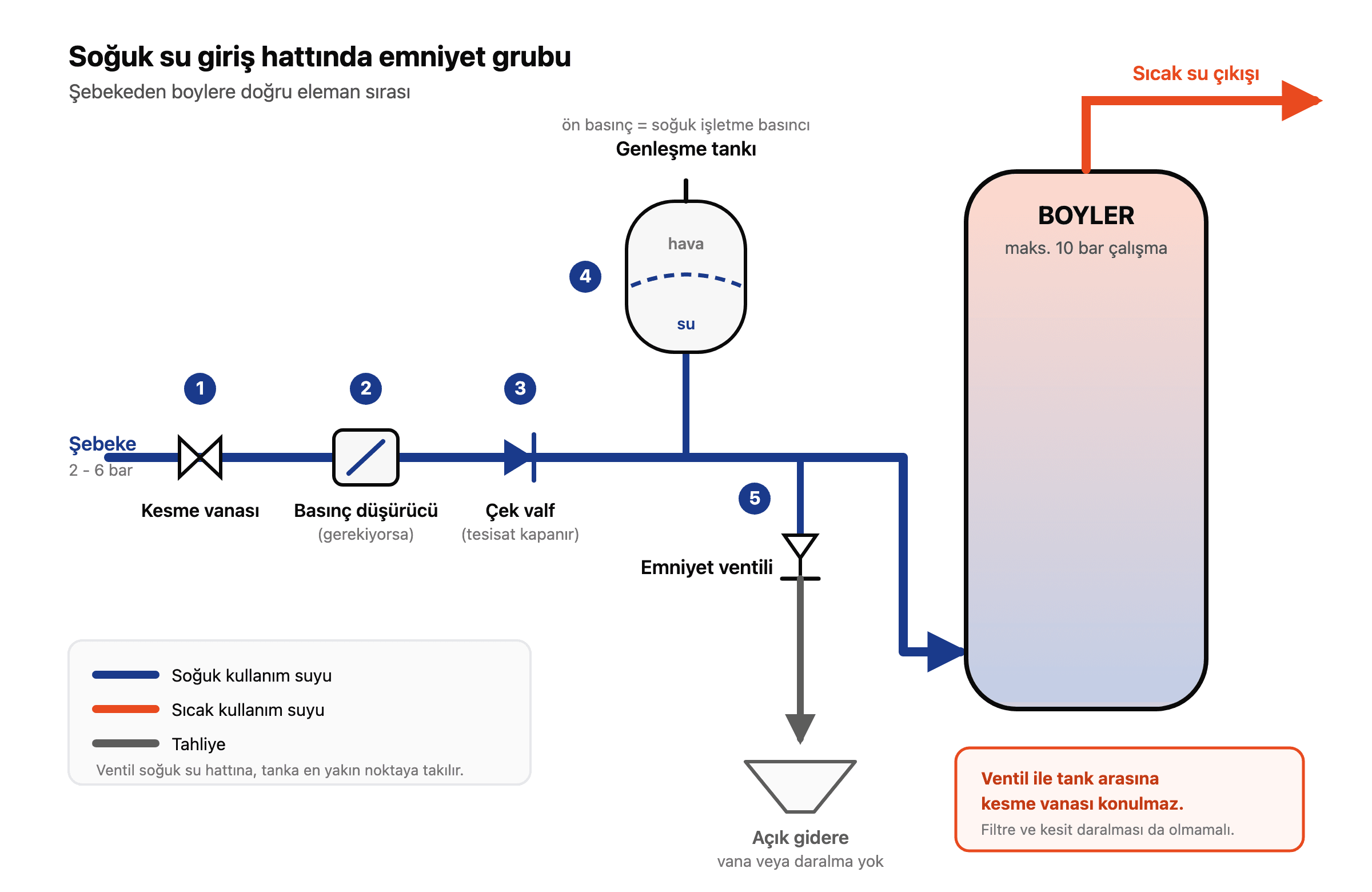
- Safety relief valve: mount it on the cold inlet line with no shut-off valve between the tank and the valve. Select it so the tank's 10 bar working pressure is never exceeded. For detailed selection and fault diagnosis see our water heater safety valve guide.
- Expansion vessel: in closed systems, fit it on the cold inlet line near the relief valve; it absorbs the expanding volume as water heats and stops the valve tripping needlessly.
- Valves and check valve: a check valve on the cold inlet stops water flowing back into the mains. A separate shut-off valve on every port is recommended so future service work is possible without draining the system.
- Insulation: Omega accumulation tanks ship factory-insulated (50 mm PU or sponge depending on capacity); insulating the connection pipes as well cuts the standing losses on the line.
- Floor and access: tanks of 1,000 liters and above are heavy even empty; check the floor's load capacity and the door and corridor widths before installation day.
- First fill: fill the tank with cold water and bleed the air first; start the heat source only after the tank is completely full. Heating an empty tank can damage the enamel lining.
Do not confuse the accumulation tank diagram with a buffer tank
The two diagrams look alike, but the water they carry differs. An accumulation tank stores domestic water; that is why it is built with an enamel lining and cathodic protection, and its ports serve the line that runs to the taps. A buffer tank holds closed-loop heating water; it needs no inner lining, and its ports sit between the boiler/heat pump and the radiator or underfloor circuit.
One facility can use both: the buffer tank stabilises the heat source while the accumulation tank stores the domestic water. We compared which facility needs which (or both) in accumulation tank vs buffer tank; the product family is on the Buffer Tank page.
Frequently asked questions
Where is an accumulation tank connected?
An accumulation tank sits between a heat source (boiler, solar system, heat pump or water heater) and the domestic hot water line. Heated water enters the upper-middle zone of the tank, cold water feeds in at the bottom, and the domestic line draws from the outlet at the top.
Should the cold water enter at the bottom or the top?
At the bottom. Hot water collects in the upper part of the tank while denser cold water stays low. Feeding cold water at the bottom preserves this layering, so the tank keeps heating the incoming water without disturbing the hot reserve above.
How many ports does an accumulation tank have?
It varies with capacity and system, but a typical tank has seven to eight connection points: cold inlet, hot outlet, heat source inlet and return, recirculation inlet, thermometer pocket, cathodic protection port and drain valve.
What does the recirculation line do?
The recirculation line continuously returns the hot water in the domestic line to the tank so it cannot cool in the pipes. Hot water then arrives the instant a tap opens; in buildings with long pipe runs, such as hotels and apartment blocks, it makes a real difference in comfort.
To lay out the connection diagram for your own facility, place the ports correctly and size the capacity, contact us or browse the full range on the Accumulation Tank page.