
Short answer
A heat pump piping diagram splits one installation into two branches. On the heating side, the flow line enters a buffer tank first; the buffer tank holds closed-circuit heating water and feeds the radiators or underfloor loops. Domestic water is heated on its own branch, through the coil of a heat pump water heater. The two bodies of water never meet. The detail most often skipped is tank selection: a heat pump delivers water at a lower temperature than a boiler, so the coil needs more heat transfer surface than a standard tank of the same size. Put the Omega single coil water heater next to the Omega heat pump water heater at matching capacities and the surface difference runs from 1.25 to 1.68 times. Below: the ports in a table, the complete system, each branch on its own, why a standard tank falls short, and what this diagram leaves out.
How to read a heat pump piping diagram
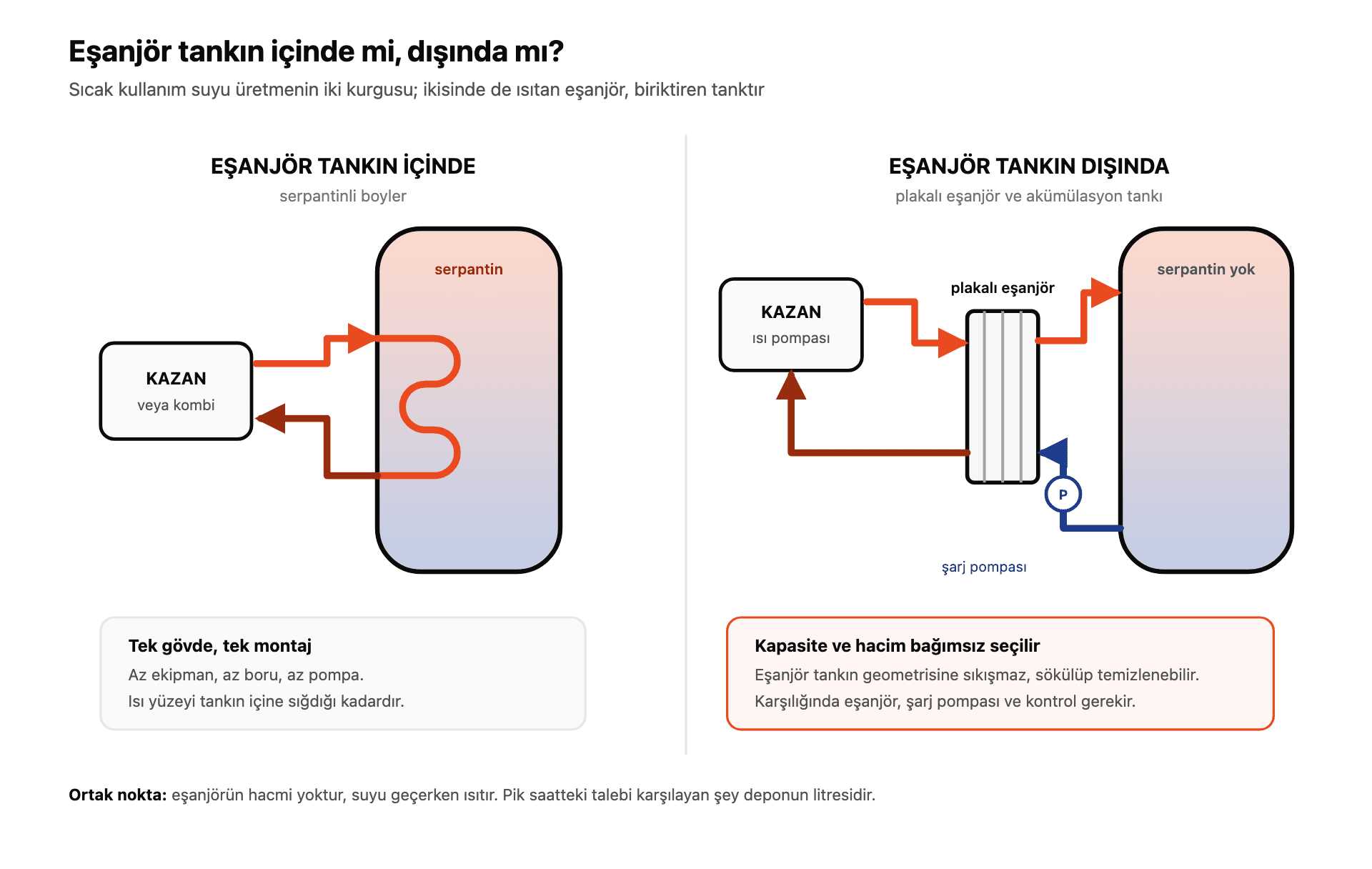
Three water circuits run through the installation, and every port belongs to one of them: the heat pump circuit, between the unit and the tanks; the heating circuit, between the buffer tank and the emitters; and the domestic circuit, mains water on its way to a tap. Work out which of the three your line belongs to before anything else. The coil is what lets two circuits trade heat without trading water, and we explained why its surface area matters in what is a heating coil.
| Port | Component | Position | Function |
|---|---|---|---|
| Heat pump flow | Heat pump | Hydraulic connection side | Sends heated circuit water out; the diagram starts here |
| Heat pump return | Heat pump | Other end of the connection | Takes back circuit water that has given up its heat |
| Buffer tank upper inlet | Buffer tank | Upper body | Admits hot circuit water from the heat pump |
| Buffer tank lower return | Buffer tank | Lower body | Sends the coldest water in the tank back to the unit |
| Heating circuit outlet | Buffer tank | Upper body, second port | Feeds the radiator or underfloor manifold |
| Heating circuit return | Buffer tank | Lower body, second port | Returns cooled water to the bottom of the tank |
| Coil supply port | Water heater | One end of the coil | Brings heat pump circuit water into the coil |
| Coil return port | Water heater | Other end of the coil | Returns the cooled circuit water to the unit |
| Cold water inlet | Water heater | Lower body | Feeds mains or booster-pump water into the tank |
| Hot water outlet | Water heater | Upper body | Sends heated domestic water to the tap line |
Each tank also carries a sensor pocket, a drain valve at its lowest point and an air vent at its highest. Port orientation and thread size vary by model, so confirm the layout against the product label before you cut any pipe.
Heat pump water heater diagram: buffer tank and water heater together
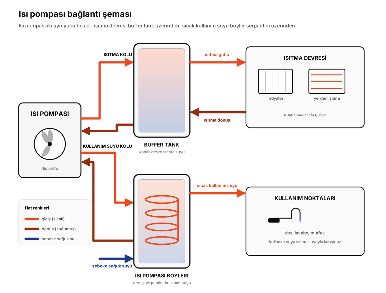 Heat pump piping diagram showing the heat pump, buffer tank, heating circuit and a separate branch feeding the coil of a domestic hot water heater
The flow line does not run to a single destination. A three-way diverter valve sends the water either to the heating branch, meaning the buffer tank, or to the domestic branch, meaning the coil. The controller is normally set to give one branch priority over the other. With domestic priority selected, heating waits while the tank reaches its set point and the valve then swings back; which priority is active is read from the controller itself.
The connection order runs as follows:
- Connect the flow line to the inlet of the three-way valve. One outlet goes to the buffer tank upper inlet, the other to the coil supply port.
- Connect the lower return port of the buffer tank to the heat pump return line, closing the heat pump circuit.
- Connect the coil return port to that same line. The two branches rejoin on the way back.
- Connect the heating circuit to the second pair of ports on the buffer tank: water leaves from the top to the emitters, the return enters at the bottom. This circuit gets its own pump.
- Connect the cold water inlet to the mains and the hot water outlet to the domestic line. An optional recirculation line returns near the hot outlet.
- Build a safety group twice over: expansion vessel and relief valve on the closed heating circuit, relief valve, check valve and expansion vessel on the cold inlet.
- Fit the sensors into their pockets and wire them to the heat pump controller, which also drives the three-way valve.
- Fill both circuits and bleed them completely before the heat pump is started.
Step four hides a mistake we see often. The domestic branch is fed straight from the heat pump flow, not from the buffer tank outlet. An extra tank in between adds another heat transfer step, and since the temperature difference on the domestic side is already narrow, that step costs output rather than buying anything.
Domestic water can also come from a plate heat exchanger and a hot water storage tank instead of a coil-type heater, which changes the port list; we covered the single-tank version in the accumulation tank connection diagram.
Buffer tank piping diagram
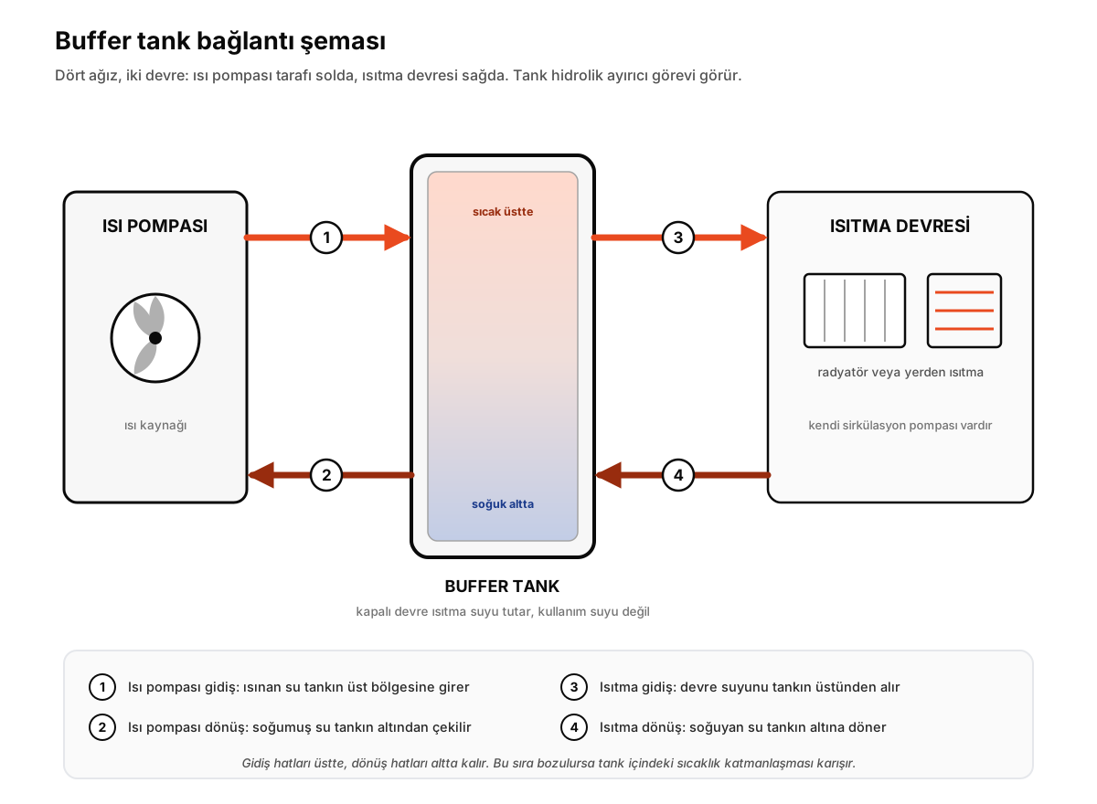 Buffer tank piping diagram with the heat pump inlet and heating circuit outlet at the top and the heating circuit return and heat pump return at the bottom
A buffer tank stores the water of the heating circuit and has no coil. No domestic water sits inside it, and no line ending at a tap connects to it. Omega buffer tanks carry neither a coil nor an enamel lining: water circulating in a closed loop is not constantly replaced, so the tank never faces the corrosion load a domestic tank does. A hot water storage tank is the opposite case, built with enamel lining and cathodic protection because it holds domestic water. We compared the two in accumulation tank vs buffer tank.
The logic of the four ports rests on stratification. Hot water is lighter and gathers at the top, cold water stays low:
- Upper inlet: the hottest water from the heat pump, feeding the top layer.
- Upper outlet: the heating circuit draws here, so the installation always gets the tank's hottest water.
- Lower return, from the installation: water cooled in the emitters enters at the bottom.
- Lower outlet, to the heat pump: the unit draws from the coldest point. The colder the return, the more heat it moves on each pass.
Those four ports make the tank a hydraulic separator, so the two circuits run at flow rates independent of each other. When room thermostats close and flow drops on the installation side, the unit keeps circulating at its own rate.
The volume matters for a second reason. Without it, the heating circuit holds only the water in the pipes and emitters, which hits its set point fast, shuts the unit down on the thermostat, cools within minutes and calls for heat again. That pattern is short cycling, the hardest way to work a compressor, and a buffer tank stretches each cycle out.
How many litres you need depends on heat pump output, the water already in the heating circuit and the heat loss of the building. We publish no multiplier because we have no verified rule of our own; choose alongside the minimum system water volume in the heat pump manufacturer's manual. Omega buffer tanks run from 50 to 5,000 litres, with 50 mm PU insulation up to 800 litres and 50 mm foam from 1,000 litres upward. The full family sits on the Buffer Tank page.
Heat pump water heater connection diagram
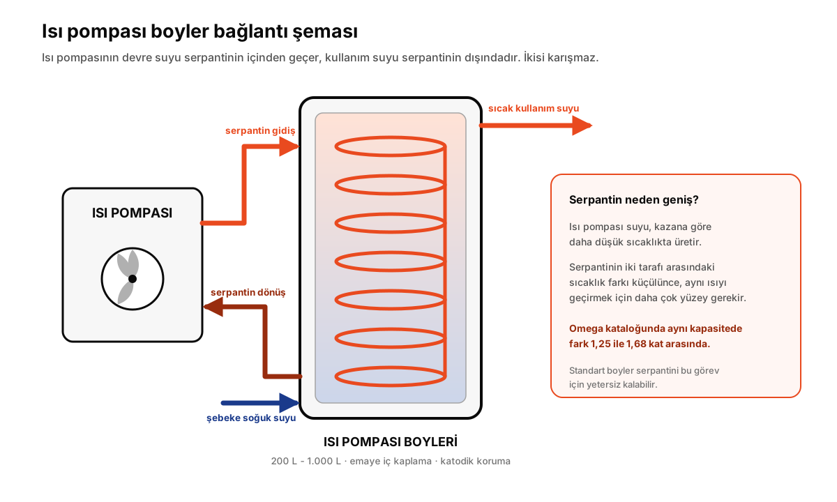 Coil connection diagram for a heat pump water heater: coil supply and return lines, cold water inlet at the bottom, hot water outlet at the top
The domestic branch is entirely separate and uses far fewer ports. Circuit water enters at the coil supply port, gives up its heat to the domestic water around it as it travels the tube bundle, and leaves at the coil return port. On the domestic side, mains water enters low and heated water leaves high. The only point of contact is the outer surface of the coil, and as long as nothing leaks, nothing mixes.
Whether the coil supply port sits high or low varies by model, so confirm it against the label first. The port logic on the domestic side matches the water heater connection diagram: check valve and relief valve on the cold inlet, drain valve at the lowest point, recirculation port on long runs.
Our coil is built for a maximum of 110 °C, tank water up to 90 °C and 10 bar working pressure. Those ratings also allow the same tank to be connected to a boiler circuit later, so a change of heat source does not mean a change of tank.
One warning. If the heat pump cannot run periodic high-temperature disinfection on its own, plan a second heat source on the domestic side, either a boiler circuit or an electric element. The disinfection temperature and interval are set in the unit's controller; take the values from the heat pump manufacturer's manual.
Why a standard water heater does not suit a heat pump
This is the most expensive mistake in a heat pump installation. The existing tank gets left where it stands, new lines are pulled to the coil ports, and then the questions start about why hot water takes so long. The answer is on the coil surface.
One side of that coil carries circuit water from the heat pump, the other the domestic water waiting to be heated, and the heat crossing between them rises with the temperature difference between the two sides. A boiler keeps that difference wide, so a small surface is enough. A heat pump never reaches those temperatures; it works noticeably below them. Our coil withstands up to 110 °C, but that ceiling exists for boiler circuits and a heat pump will not press against it. What the unit actually delivers depends on the model, the outdoor temperature and the controller settings, so we put no figure here; that number belongs in the heat pump manufacturer's manual. The direction is what matters. The difference narrows, and once it narrows, one remedy remains: more surface to move the same heat.
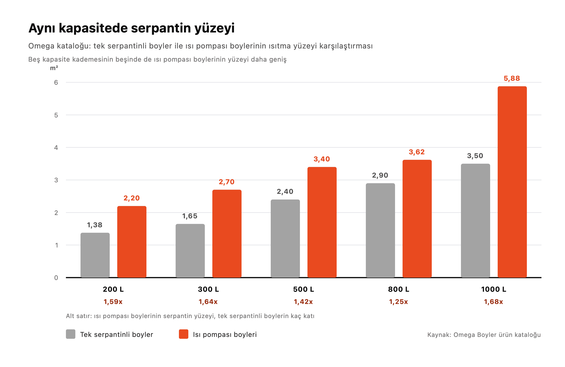
As the manufacturer of the tank, we can see this in measurable terms in our own catalogue:
| Capacity | Single coil water heater | Heat pump water heater | Ratio |
|---|---|---|---|
| 200 L | 1.38 m² | 2.20 m² | 1.59 |
| 300 L | 1.65 m² | 2.70 m² | 1.64 |
| 500 L | 2.40 m² | 3.40 m² | 1.42 |
| 800 L | 2.90 m² | 3.62 m² | 1.25 |
| 1,000 L | 3.50 m² | 5.88 m² | 1.68 |
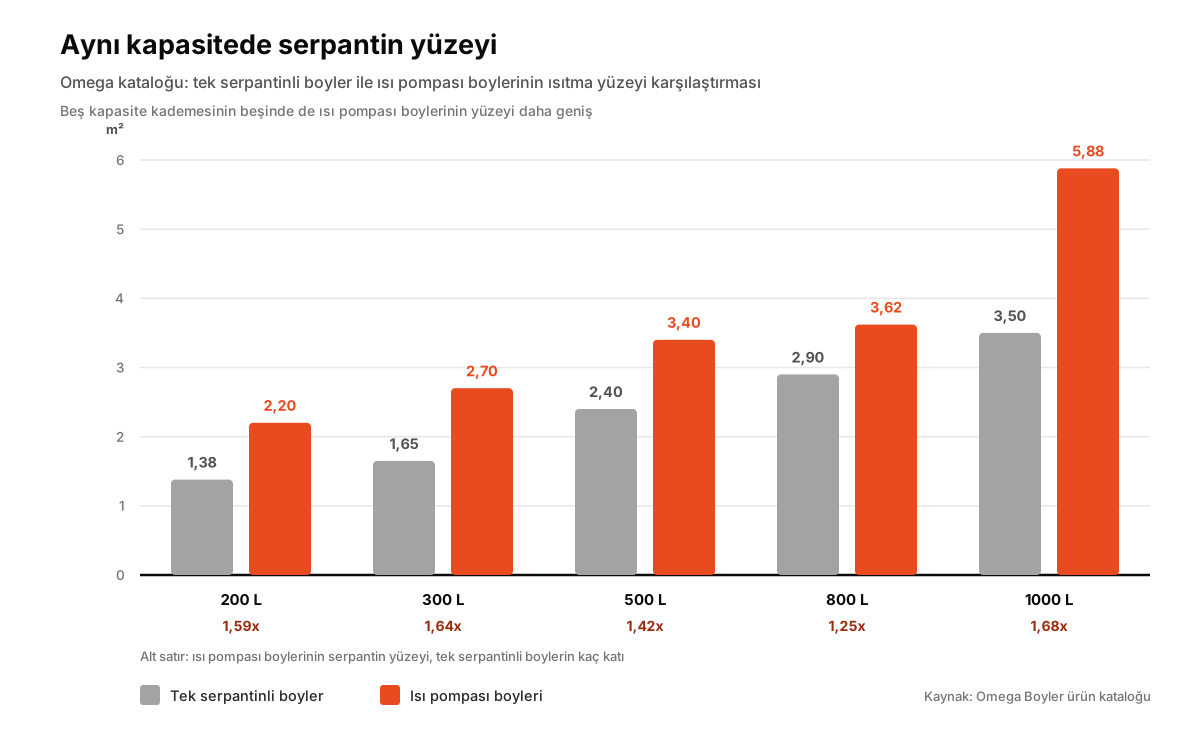 Omega catalogue comparison of coil surface area between the single coil water heater and the heat pump water heater at matching capacities
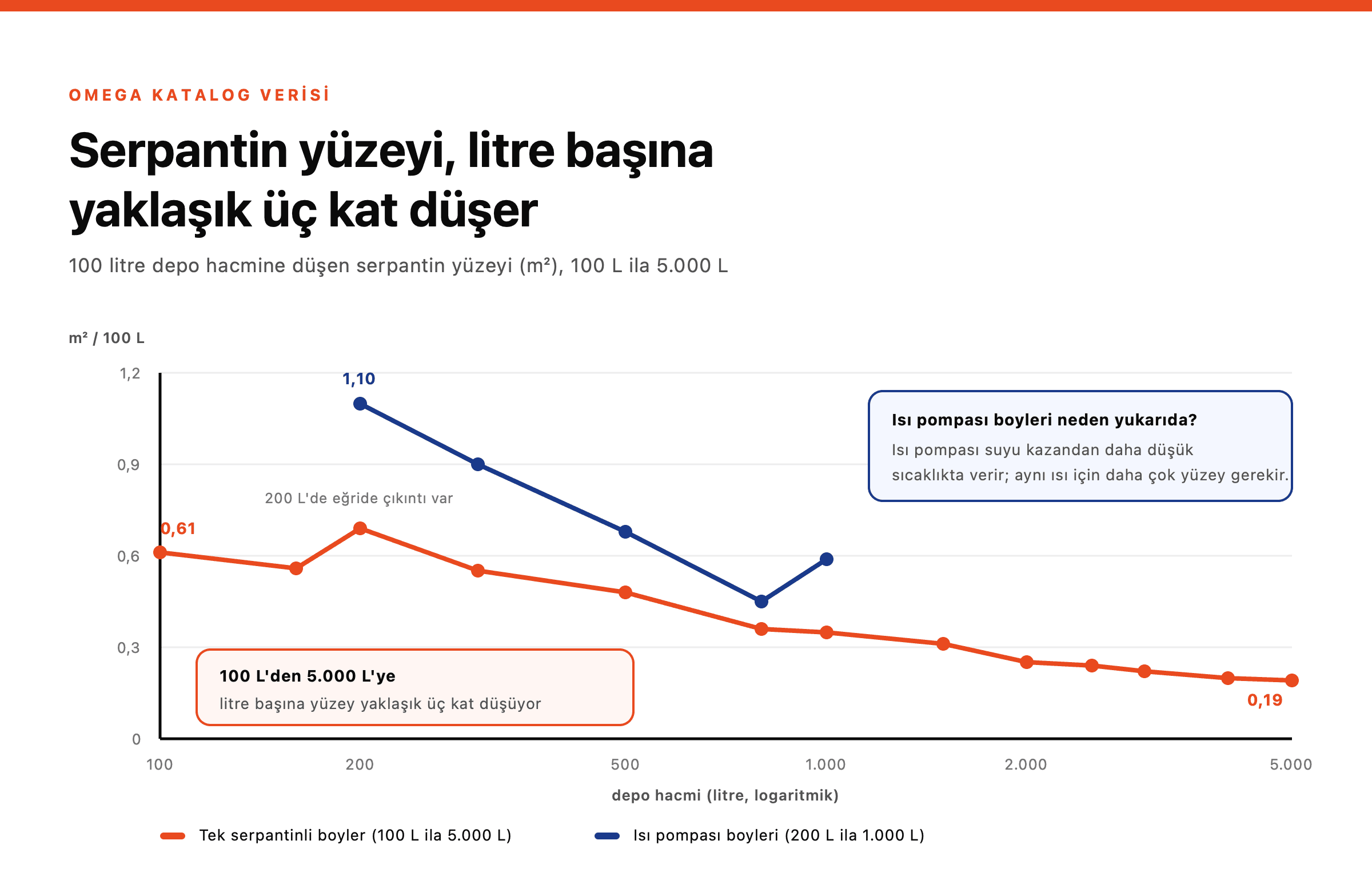
In all five capacity steps the heat pump water heater carries the wider coil. The gap ranges from 1.25 to 1.68 times and averages 1.52. It reads the same way per litre: at 200 litres the single coil tank offers 0.69 m² per 100 litres, the heat pump tank 1.10 m².
Connect a standard tank anyway and the coil lacks the surface to pass the required heat at the temperature the heat pump supplies. Reheat takes longer, the unit runs longer, and at peak demand, the morning shower hour for instance, the tank never reaches its set point. The larger the building, the faster that delay turns from a comfort complaint into a capacity problem.
One boundary stated plainly: Omega does not manufacture heat pumps, only the tanks that connect to them. The table above is surface data for our product, not a claim about heat pump performance. The complete technical table sits on the Heat Pump Water Heater page; for picking a step, our water heater selection guide and water heater calculator help.
Critical rules for a heat pump installation
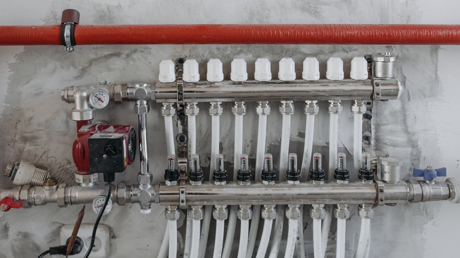 Underfloor heating manifold with a flow meter per circuit, circulation pump, pressure gauge and insulated flow line
- Heating water and domestic water stay in separate vessels. No Omega model combines the two in one shell, so two tanks on the diagram is normal.
- Every circuit gets its own safety group. Heating side and domestic side each need a relief valve and an expansion vessel. Set pressure and weeping valves are covered in our water heater safety valve guide.
- Air is the main enemy here. Air left in a circuit drops the flow rate and spoils heat transfer. Put automatic vents at the high points and purge fully on first fill.
- Fit a filter on the return line. A dirt separator or magnetic filter catches particles and sludge coming back from the installation and protects the heat pump's exchanger. Clean it in the first months.
- Flow rates follow the heat pump manufacturer's manual. Pipe sizes, pump selection and minimum system water volume are the unit manufacturer's values, not ours; tank volume is an input to that calculation.
- An isolating valve on every port. Separate valves on the inlet, outlet, coil and heating lines mean an anode change does not require draining the installation.
- Insulate the pipework. Tanks ship insulated, connection pipes do not. An uninsulated run is pure loss in a system whose temperature difference is already narrow.
- Measure the floor and the route in advance. The 1,000 litre heat pump water heater weighs 312 kg dry, stands 2,100 mm tall and is 950 mm in diameter. Buffer tanks get heavier: the 5,000 litre tank is 900 kg dry, 2,850 mm tall, 1,650 mm across. Check door widths, ceiling height and floor load capacity before delivery day.
- The commissioning order does not bend. Never start the heat pump before the tanks and circuits are completely filled; dry running damages the coil and the enamel lining.
What this diagram does not cover
Everything above concerns the hydraulic side. What it leaves out:
- Electrical connection and fuse sizing. Cable cross-section, fuse rating and residual current protection belong to the manufacturer's manual and a licensed electrician.
- The refrigerant circuit. The line between outdoor and indoor units, with evacuation and charging, is authorised service work.
- Commissioning and parameters. Set points, heating curve, three-way valve priority and the disinfection programme live in the heat pump controller.
- Performance figures. Omega does not manufacture heat pumps, so we publish no efficiency value, electricity consumption or savings figure for the unit; that data sits in the equipment manufacturer's documentation.
- Project-specific calculation. Tank volumes come out of a heat loss and usage profile calculation. This article describes a typical arrangement and is not a project drawing.
Frequently asked questions
Does a heat pump need a buffer tank?
Not on every installation, but in practice yes when the heating circuit holds little water of its own. With too little volume the unit starts and stops at short intervals, a pattern called short cycling, and it is the hardest way to work a compressor. A buffer tank lengthens each cycle and cuts the starts per hour. The effect is clearest in underfloor heating, where room thermostats close frequently.
What is the difference between a heat pump water heater and a standard one?
The coil surface. In the Omega catalogue, at matching capacity, the coil in a heat pump water heater offers 1.25 to 1.68 times the surface of a single coil tank, averaging 1.52 across the five steps. A heat pump produces water at a lower temperature than a boiler, so the temperature difference across the coil narrows and moving the same heat takes more surface. Shell dimensions stay the same.
Is a buffer tank the same as a hot water storage tank?
No. A buffer tank holds closed-circuit heating water and has neither a coil nor an enamel lining, because the water inside is not continually replaced. A hot water storage tank holds domestic hot water, so it is built with enamel lining and cathodic protection. Both can sit in the same plant room: the buffer tank steadies the heat source, the storage tank holds the water going to the taps.
What size buffer tank do I need?
Heat pump output, the existing water volume of the heating circuit and the heat loss of the building decide it together. We give no single multiplier because we have no verified rule for it; the minimum system water volume in the heat pump manufacturer's manual is the place to start. Omega buffer tanks are produced between 50 and 5,000 litres.
Can a heat pump do heating and hot water at once?
In a typical installation, no, it does them in turn. A three-way diverter valve points the flow line either at the buffer tank or at the coil, never at both. Where domestic priority is set in the controller, heating waits until the tank reaches its set point and the valve then swings back. That is why the reheat time of the tank also shapes heating comfort.
What capacities does the heat pump water heater come in?
Omega builds it in 200, 300, 500, 800 and 1,000 litre steps, with coil surfaces of 2.2, 2.7, 3.4, 3.62 and 5.88 m² respectively. All ship with enamel lining, magnesium anode cathodic protection and 50 mm PU insulation.
Pipe sizes, pump selection and tank volumes on your own project shift with the heat loss of the building. When you choose the two tanks on the hydraulic side, open the technical tables on the Heat Pump Water Heater and Buffer Tank pages side by side: the capacity steps and the weights settle the installation question early. Send us the capacity you are working with and we will pick the step together, via contact us.