
Short answer
A water heater connection diagram shows which line each port on the tank pairs with: cold water enters at the bottom, heated water leaves from the top into the hot water line. On coil-type tanks, the hot circuit water coming from a boiler or solar collector enters through the coil supply port and returns through the coil return port; this circuit never mixes with the domestic water. An electric water heater has no coil ports; instead, an immersion heating element and a thermostat connect to the electrical supply. Whatever the type, the safety relief valve, the drain port and, where fitted, the recirculation connection are fixed parts of the diagram. Below we walk through the connection points for each tank type, step by step.
How to read a water heater connection diagram
A typical tank label or technical drawing marks 6 to 9 ports. We covered the basics of coils, enamel lining and cathodic protection in our what is a water heater article; here we focus directly on the connections.
| Port | Position on tank | Function |
|---|---|---|
| Cold water inlet | Lower body | Feeds mains water into the tank; the tank fills from this point |
| Hot water outlet | Upper body | Heated water collects at the top by density and leaves for the taps from here |
| Coil supply port | One end of the coil (upper or lower by type) | Brings hot circuit water from the boiler, combi or solar collector into the coil |
| Coil return port | Other end of the coil | Sends the cooled circuit water back to the heat source |
| Recirculation port | Near the hot water outlet | Returns cooled water waiting in the line back to the tank so hot water arrives instantly |
| Safety relief valve | On the cold water inlet line | Discharges water when tank pressure exceeds the set value, protecting the vessel |
| Thermometer/thermostat pocket | Body, near the top | Sensor pocket for temperature reading and thermostat control |
| Magnesium anode | Top cover, near the sensor pocket | Mounting point of the sacrificial rod that provides cathodic protection |
| Drain port | Lowest point of the tank | Allows the tank to be fully emptied for service or repair |
These nine ports repeat across single-coil, double-coil and electric models; the difference lies in the number of coils, and in the electric model the heating element takes the coil's place.
Boiler connection diagram (single coil)
Connecting a boiler is the most common installation for a single coil water heater: one heat source (boiler or combi) feeds the coil while the domestic water stays in its own circuit.
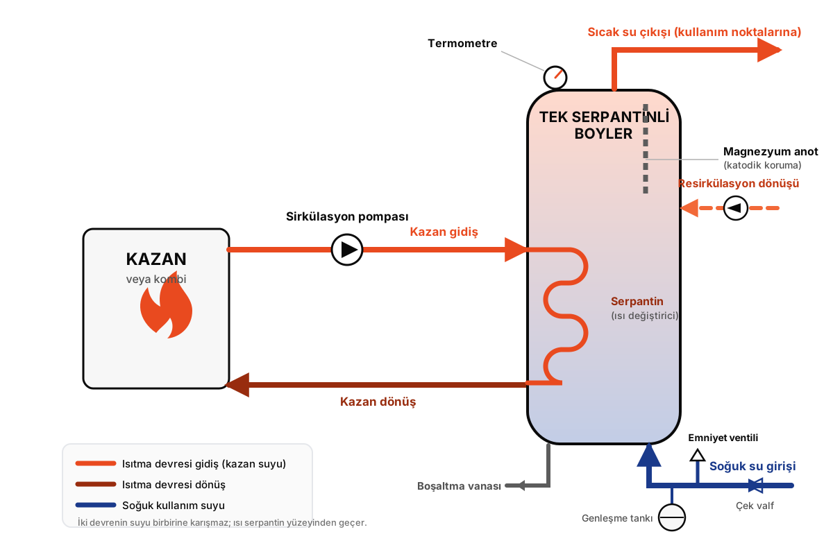 Single coil water heater to boiler connection diagram: boiler supply and return lines, circulation pump, cold water inlet and hot water outlet
The connection order runs as follows:
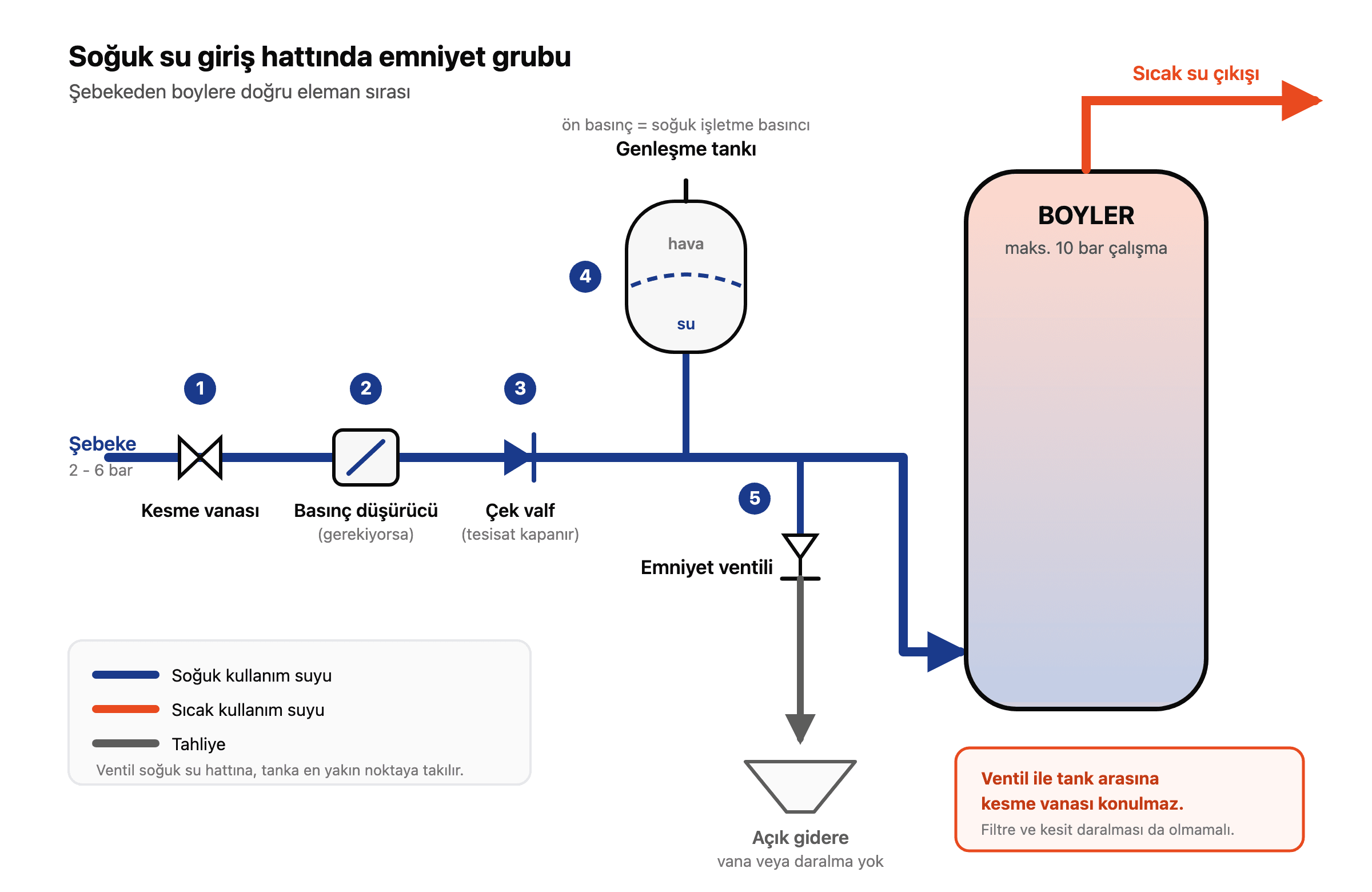
- Connect the cold water inlet to the mains line, with a check valve and a shut-off valve on the line.
- Mount the expansion vessel on the cold water inlet line, close to the safety relief valve.
- Fit the safety relief valve on the cold inlet line and route its discharge to a drain.
- Connect the boiler supply line to the coil supply port and the return line to the coil return port, adding a circulation pump and shut-off valves to the circuit.
- Connect the hot water outlet to the domestic line; if needed, connect the recirculation line to the second port near it.
- Place the sensor in the thermometer/thermostat pocket and wire it to the boiler control.
- Fill the whole system with water and bleed the air before starting the boiler.
This order is not optional: the tank and the coil must be full of water before the boiler is fired, otherwise dry running damages the coil.
Double coil water heater connection diagram (solar + boiler)
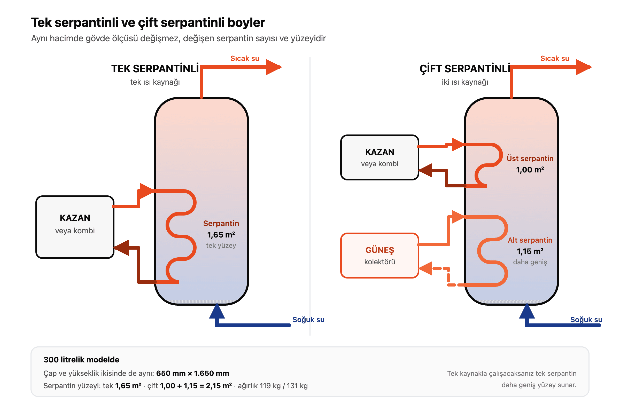
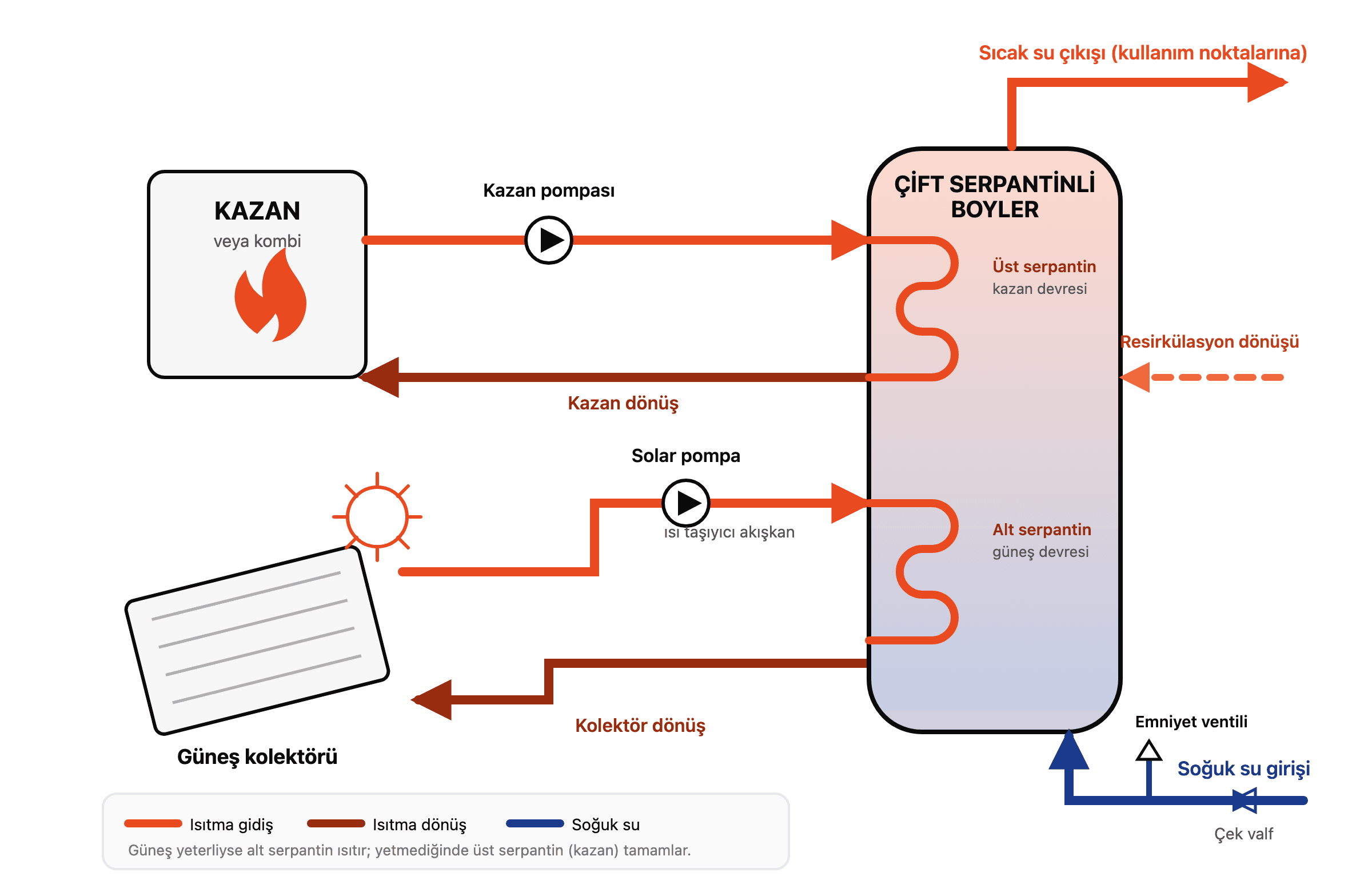
In a double coil water heater, two separate coils connect to two different heat sources at the same time. The most common setup combines a solar collector and a boiler (or combi) in one tank.
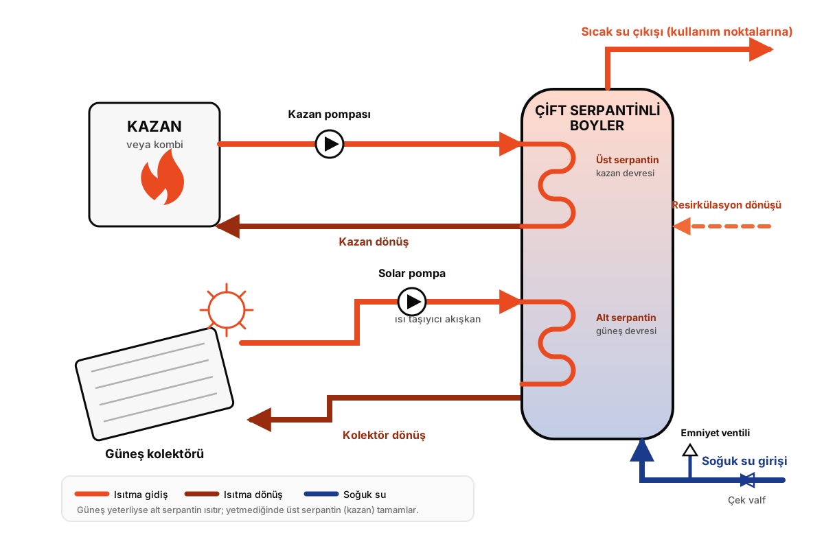 Double coil water heater connection diagram: the lower coil connects to the solar collector, the upper coil to the boiler
The layout follows this logic:
- The lower coil connects to the solar collector (pre-heating): heat-transfer fluid from the rooftop collector enters the lower coil. The lower zone of the tank sits next to the cold inlet, so the water is pre-heated here first.
- The upper coil connects to the boiler (top-up): when the sun cannot deliver the target temperature, the boiler or combi circuit takes over and finishes the job through the upper coil.
This arrangement is not arbitrary. Solar energy arrives at varying intensity through the day, so it pre-heats the bulk of the tank; the boiler then lifts the water to the final temperature with steady, controlled heat. When solar is sufficient the boiler may not run at all, and on overcast days the system still delivers hot water without interruption. Each circuit needs its own circulation pump and shut-off valves, so one can keep working while the other is serviced.
Electric water heater connection diagram
An electric water heater has no coil; the heat source is an immersion element inside the tank. The water side of the diagram gets simpler, while the electrical side demands separate care.
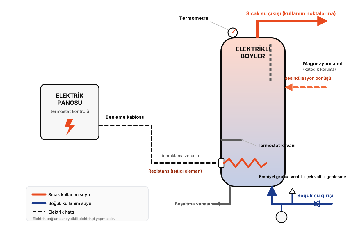 Electric water heater connection diagram: heating element, thermostat and safety group connections
On the water side there are the cold inlet, hot outlet, safety relief valve, drain and, where fitted, a recirculation port; there is no coil supply/return line. The element mounts on a flange fixed to the tank body; the thermostat switches it on and off automatically to hold the set temperature.
The electrical connection requires its own fuse and earthing line sized to the element power (Omega electric water heaters range from 5 kW to 45 kW). This connection must be made by a licensed electrician in line with the applicable electrical installation code. A wrong fuse or missing earth puts both the unit and the user at risk; even if the water side is complete, do not wire the electrical side yourself.
Critical rules for water heater installation
Installed in the right order, a water heater runs trouble-free for years. The points most often skipped are:
- The safety relief valve is mandatory: every installation needs a relief valve on the cold inlet line, set below the tank's working pressure (max. 10 Bar on Omega tanks); its discharge must never be capped and should run to a drain. How the set pressure is chosen and why the valve weeps is covered in our water heater safety valve guide.
- An expansion vessel is required: in closed systems water expands as it heats. A diaphragm expansion vessel near the relief valve absorbs that extra volume; without it, pressure keeps tripping the valve and wasting water.
- A check valve stops backflow: fitted on the cold inlet, it prevents hot tank water from escaping back into the mains.
- Valve placement eases servicing: a separate shut-off valve on the inlet, outlet and each coil line means future maintenance or an anode change does not require draining the whole installation.
- Insulate the pipework too: the tank ships insulated from the factory, but uninsulated connection pipes leak heat; pipe insulation is the most overlooked part of the job.
- Commissioning order matters: never start the heat source (boiler or element) before the installation is completely filled and bled; dry running causes permanent damage to the coil or element.
Frequently asked questions
How is a water heater connected to a boiler?
The boiler's supply line connects to the tank's coil supply port and its return line to the coil return port. Heat passes between the two circuits only through the coil surface; boiler water and domestic water never mix. A circulation pump is usually added to the circuit.
Where is the safety relief valve installed?
On the cold water inlet line, between the tank and the check valve. When tank pressure exceeds the set value it discharges water and protects the vessel. Its outlet must run to a drain and must never be capped.
Is a recirculation line required?
It is not mandatory, but it is recommended for comfort on long pipe runs. The recirculation line sends the cooled water waiting in the pipes back to the tank, so hot water arrives the moment a tap opens; short, single-point systems usually do not need one.
Does a water heater need an expansion vessel?
In closed systems, where mains pressure has nowhere to relieve itself, yes. Water expands as it heats; without an expansion vessel to absorb that volume, the pressure repeatedly trips the relief valve and wastes water.
Which way should the coil supply and return run?
Hot water from the heat source enters through the coil supply port and, after giving up its heat, returns to the source through the return port. On double coil tanks the lower coil usually serves the solar collector and the upper coil the boiler; confirm the exact direction against the port markings on the product label.
Reading the connection diagram correctly settles most of the installation, but pipe sizes, valve counts and pump selection change with capacity. You can size your tank with our water heater calculator, read the companion piece on the accumulation tank connection diagram, or contact us for a connection plan tailored to your project.